Here is a block diagram of my vacuum tube home theater system. Thought this might be interesting to share.


A great find! Can't wait to see it working.

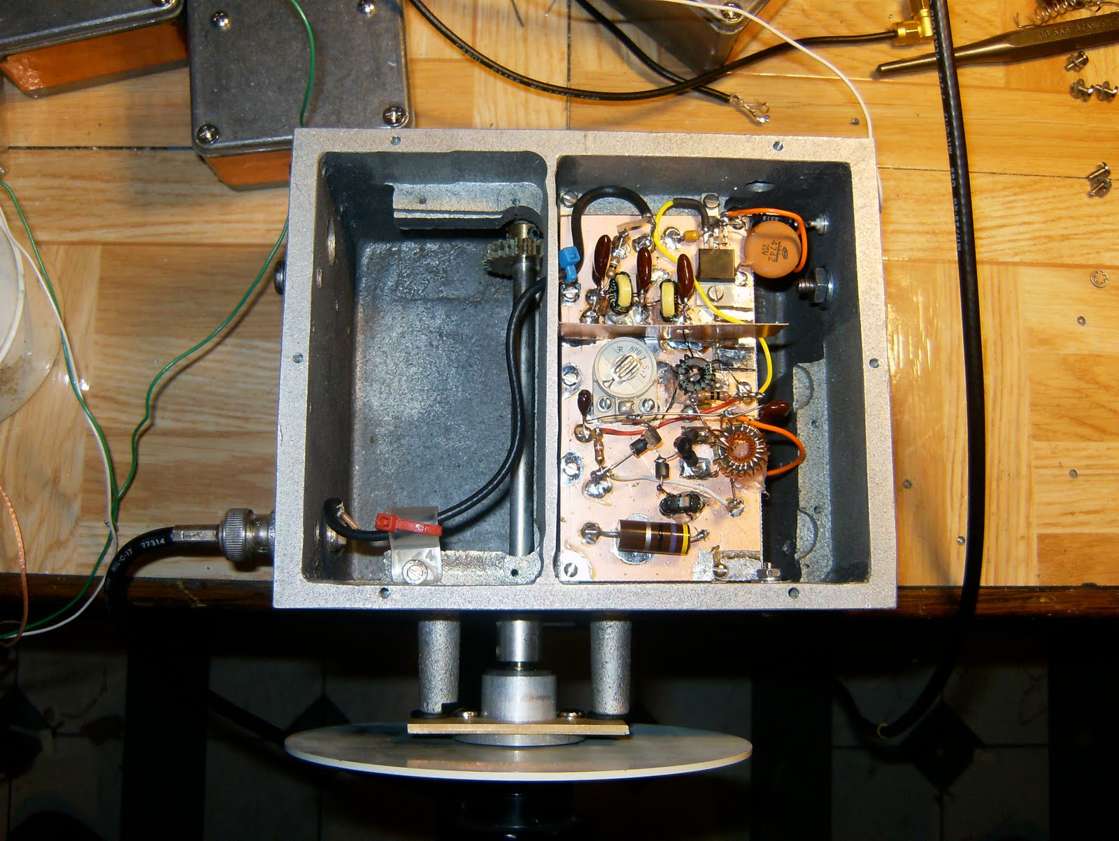

Photos from the top:
1. VFO
2. insides
3. connected to the rest of the modules that make up my 20 M SSB
radio project.
Results:
Works great! I found that cheaper 2n4124's (or equivalent) NPN
transistors work better than UHF low-noise transistors. This was
indicated in the ARRL handbook, but, i chose to ignore it and hoped
to improve phase noise performance by using the low-noise UHF
transistors. The problem with the UHF transistors was that they
would output broad-band oscillations on occasion causing instability
in the VFO. So, best approach is to follow the directions from the
handbook and go with the cheap transistors for this type of VFO.


Oscillator signal chain includes: oscillator circuit -> mmic
amplifiers -> LPF -> RF out at 10 dBm.
Photos (from top down):
1. inside of the oscillator
2. outside of oscillator
3. oscillator connected to SSB radio signal chain. works great!