Friday, September 30, 2011

ARRL Homebrew 3 Challenge update: TR sequencing circuit

As soon as i installed my fast acting VSWR protection circuit i started tripping it when i was feeding my LPF & TR assembly.  There were moments where, the TR relay was not engaged but the PA was already biased and transmitting.  This would cause an instantaneous VSWR fault detected by the VSWR protection circuit, which would shut down the PA bias.

For this reason i had to add a delay which would turn on the bias to the PA after a short duration and which would keep the TR relay on for a while after the PA bias was shut off (see green board located below the PA itself).


It is certainly a challenge, TR switching a 100 watt + PA.

Wednesday, September 28, 2011

ARRL Homebrew 3 Challenge Update: VSWR protection circuit

Had to install a VSWR protection circuit to protect the 100 watt output transistor from greater than 10:1 reflection.

The comparator measures VSWR, trips an S/R flip-flop which then biases an NMOS that shorts out the bias supply varactor diode regulator circuit, thereby turning off the PA.  A buzzer sounds to indicate VSWR fault.

To reset, the power must be cycled on the radio.


Monday, September 26, 2011

Best Paper Award, Tri-Services Radar Symposium 2010

I was surprised to find out this summer that we won best paper at the 2010 Tri-Services Radar Symposium for our work on the real-time through-wall radar imaging system.

We hope that others will consider this work as a potential solution to the thru-wall problem given the results we have achieved thus far.

Here is a press release.

Link to information on the thru-wall radar system.

Link to some thru-wall 'radar videos.'

Friday, September 23, 2011

ARRL Homebrew III Challenge Update: Cleaning up transmit spurs

TX spurious emissions test

front panel of 10m/6m SSB/CW ARRL homebrew challenge 3 challenge entry

I've spent the past two weeks working on mitigating spurious emissions from the transmitter at 6m.  The specification for 6m is to have the spurs at least 60 dB below carrier.  This radio may be unusual compared to other homebrew challenge 3 radio entries in that it has a 100 watt transmitter rather than the specified 25 watts.  For this reason there are multiple driver stages, some of which are driven into compression, amplifying and multiplying transmit mixer spurs.  Great care was taken in the strategic placement of filters to eliminate these to meet spec.

Now that the transmitter is clean i hope to have this radio on the air soon.  Stay tuned.....

Tuesday, September 20, 2011

Radar Short Course at MIT

More feedback on our 1-week radar course, where you learn about radar while making one.

We are preparing for next summer's courses, where we will run an improved version of this course and offer a new phased array course, where everyone learns by making their own small phased array radar system.

Saturday, September 17, 2011

Heathkit is back!


heathkit.png


I first read about this in IEEE spectrum,

good news:  Heathkit will be making kits again soon...

"Thank you for your overwhelming response to our announcement that Heathkit is back into the Do-it-Yourself kits business. We received many great suggestions for kits you would like to build.
We will be releasing Garage Parking Assistant kit (GPA-100) in late September and soon after the Wireless Swimming Pool Monitor kit will be available.
Based on your input, we are looking at developing amateur radio kits. Our goal is to have kits available by the end of year.
Please keep your suggestions coming so that we can continue to bring you interesting, unique Heathkit products."

Monday, September 12, 2011

Education Society and IEEE Women in Engineering: The MIT IAP 2011 Radar Course: Build a Small Radar System Capable of Sensing Range, Doppler, and Synthetic Aperture Radar (SAR) Imaging

Tomorrow at Tufts i will be presenting a talk on the coffee can radar course:

This will be a fun talk with a spirited discussion on both how to make a radar out of coffee cans and also how to use it to teach the basics of radar and applied electromagnetics.


Education Society and IEEE Women in Engineering

3:00 PM

Tuesday, 13 September

The MIT IAP 2011 Radar Course: Build a Small Radar System Capable of Sensing Range, Doppler, and Synthetic Aperture Radar (SAR) Imaging

Dr. Gregory L. Charvat, MIT Lincoln Laboratory

Recently, MIT Lincoln Laboratory sponsored a radar short course at MIT main campus during the 
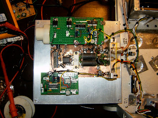
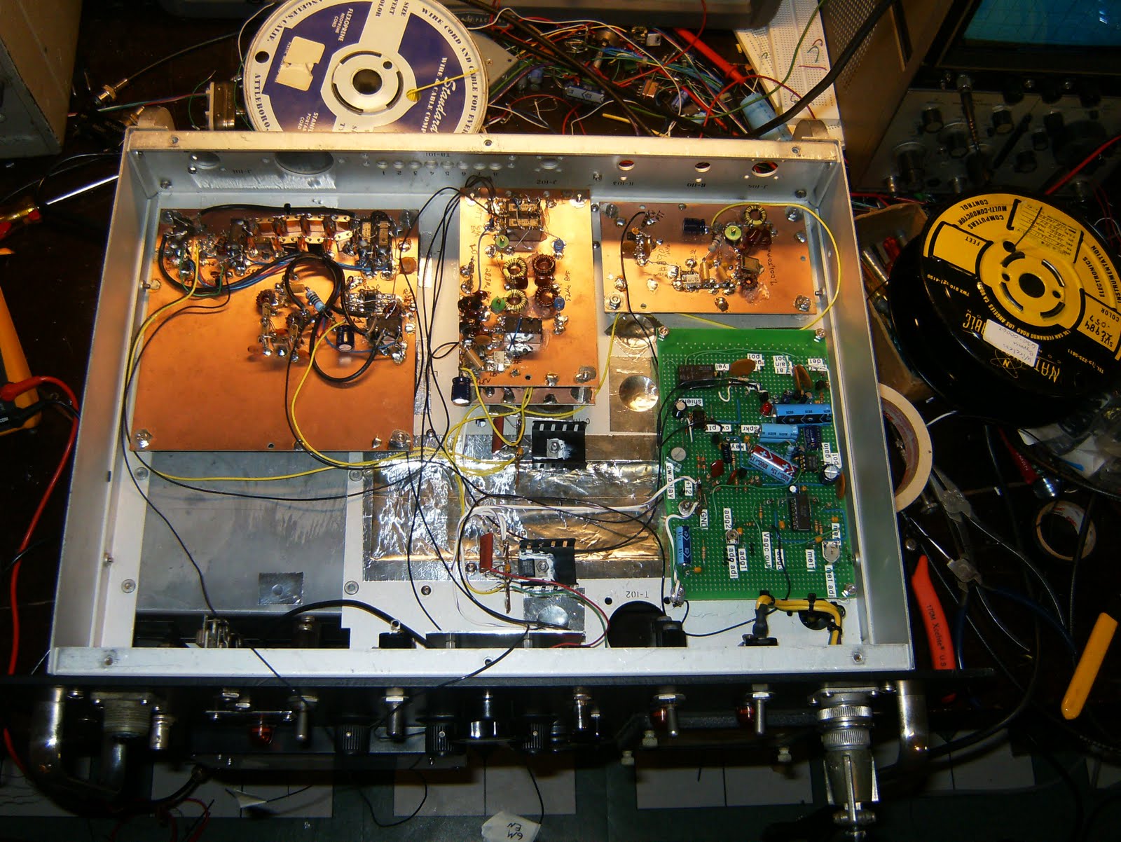
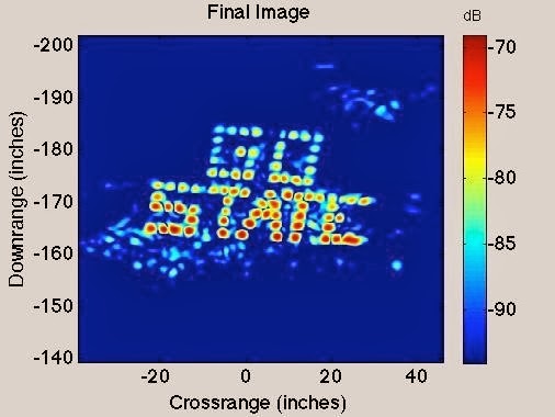
January 2011 Independent Activities Period (IAP). The objective of this course was to generate student interest in applied electromagnetics, antennas, RF electronics, analog circuits, digital signal processing, and other engineering topics by building a short-range radar sensor and using it in a series of field tests. Lectures on the basics of radar, modular RF design, antennas, pulse compression and SAR imaging were presented. Teams of three students received a radar kit. This kit was developed by the authors and uses a frequency modulated continuous wave (FMCW) architecture. To save costs, empty metal coffee cans are used for antennas, parts are mounted on a wood block, it uses only 6 coaxial microwave parts, analog circuitry on a solderless breadboard, and runs on 8 AA batteries. Data is acquired by the audio input on a laptop computer sampling the video output (right channel) and transmit synchronization pulses (left channel). The total cost of each kit was $360. Of the nine student groups, all succeeded in building their radar, acquiring doppler vs. time and range vs. time plots, seven succeeded in acquiring at least one SAR image, and some groups improved the radar system itself. Great interest in these topics was generated by this course. By presenting these difficult topics at a high level while at the same time making a radar kit and performing field experiments, students became self motivated to explore these topics. In the long term, courses using this continuous engagement philosophy could help fill the gap as the current generation of radar engineers continues to retire.
Dr. Gregory L. Charvat PhotoGregory L. Charvat grew up in the metro Detroit area, where the hands-on approach to engineering within the automotive culture was a great influence on his life. He earned his PhD in electrical engineering in 2007, his MSEE in 2003, and BSEE in 2002 from Michigan State University where he worked as a graduate research assistant for the Electromagnetics Research Group. He is currently a technical staff member at MIT Lincoln Laboratory since September of 2007 and teaches short radar courses at the Massachusetts Institute of Technology.
This meeting of the Boston chapter of Education Society and the IEEE Women in Engineering Boston Affinity Group is scheduled for 3 PM, Tuesday September 13th at Tufts University, Halligan Hall, Room 111 Department of Electrical and Computer Engineering, 161 College Avenue, Medford, MA 02155. It is free and open to the public. For more information, contact IEEE Boston Section Chair and Chair, Education Society, Dr. Karen Panetta, (Karen@ieee.org)
Directions to the Tufts University are available at http://www.eecs.tufts.edu.
Halligan Hall is located across the street from the Cousen’s parking lot, and is adjacent to the Tufts Cousen’s Gymnasium.

Saturday, September 10, 2011

Radar Short Course at MIT

Reviews are in from our radar course: we were the top ranked MIT Professional Education short course this year!

Saturday, September 3, 2011

ARRL Homebrew 3 Challenge update: system level trouble shooting


Everything worked well on the bread board, why does it not work when installed into the chassis?

This is why system level trouble shooting must be performed after system integration.  In this case i have measured significant loss in sensitivity, what could be the cause?  

Only a few more hours and another cup of coffee will tell.  

Stay tuned.....

Thursday, September 1, 2011

ARRL Homebrew 3 Challenge update: wiring it together


I'm now wiring up all of the modules.  This is a very tedious process but must be done carefully.

From the top photo; front panel with the main power light and the LCD lights; bottom of the radio showing the RF/IF/Prod/audio/agc mostly wired; the VFO board being modified to access I/O pins and the 'function' button.

Next step:  complete wiring then trouble shooting of the system, starting with power amplifiers and working way down to the RF/IF.